


Views: 0 Author: Site Editor Publish Time: 2026-07-07 Origin: Site


In twin-screw extrusion, the difference between a high-yield, homogenous compound and a degraded, off-spec batch often comes down to the precise configuration of the mixing zone. Process engineers and plant managers frequently struggle with balancing dispersive and distributive mixing without exceeding the thermal degradation limits of the polymer. Incorrect element selection leads to excessive shear, localized hot spots, pressure spikes, premature wear, or poor additive dispersion. Evaluating the specific mechanical actions, flow behaviors, and shear profiles of SME TME ZME screw elements is critical for optimizing co-rotating twin-screw profiles. This guide breaks down the technical specifications, performance trade-offs, and process-specific use cases for each element to inform your next tooling investment.
SME (Screw Mixing Elements) prioritize distributive mixing with minimal shear, making them optimal for heat-sensitive materials and downstream filler incorporation.
TME (Turbine Mixing Elements) deliver a balanced combination of dispersive and distributive mixing through moderate-to-high shear, ideal for breaking down tough pigment agglomerates.
ZME (Toothed Mixing Elements) excel in high-intensity distributive mixing and back-mixing, specifically engineered for liquid injection and blending components with highly disparate viscosities.
Alternative to Kneading Blocks: These specialized mixing elements for compounding offer alternative shear-rate distributions compared to standard kneading blocks (KBs), allowing for precise temperature control.
Strategic Configuration: High-performance compounding lines utilize a sequential combination of these elements based on the polymer's rheological profile, viscosity ratio, and required residence time.
Defining the baseline requirement is the first step in screw profile design. Dispersive mixing requires high shear stress to break down solid particles like agglomerates and fillers. You apply intense mechanical force to shatter these cohesive bonds. Distributive mixing requires spatial rearrangement. You fold and split the melt stream to blend materials evenly without applying high shear. Most compounding processes demand a specific ratio of both mechanisms to achieve final product quality. When operators run highly filled compounds, they must balance these two forces to prevent polymer degradation while ensuring uniform filler distribution.
To understand the practical application on the shop floor, consider processing a 40% talc-filled polypropylene. If you rely entirely on dispersive forces, the polymer matrix overheats, and the melt flow index shifts out of specification. If you rely solely on distributive forces, the talc clumps remain intact, causing surface defects in the final molded part. You must select elements that provide the exact mechanical action required for the specific formulation.
Mixing Type | Primary Mechanism | Target Application | Risk of Overuse |
|---|---|---|---|
Dispersive | High shear stress, particle breakdown | Pigments, hard agglomerates | Polymer degradation, excessive heat |
Distributive | Spatial rearrangement, folding, splitting | Heat-sensitive resins, fragile fillers | Poor agglomerate breakdown, unmelts |
Standard kneading blocks generate high peak shear forces at the tip clearance. They force the polymer over a tight gap, creating intense friction. Specialized mixing elements for compounding redistribute energy more uniformly. Instead of relying solely on tight clearances, they utilize slots, teeth, and reverse pitches to manipulate the melt. This structural difference prevents localized overheating and provides better control over the energy applied to the polymer matrix.
When you configure a screw profile, replacing a wide-disc kneading block with a specialized toothed element changes the energy dynamics entirely. Kneading blocks act like hammers, smashing particles through brute force. Toothed and slotted elements act like scissors, cutting and folding the melt stream repeatedly. This fundamental difference allows engineers to process temperature-sensitive materials like PVC or cross-linked polyethylene without triggering premature cross-linking or burning.
Mixing elements directly influence viscous dissipation and localized heating. Every time you shear a polymer, you generate heat. Success dictates achieving spatial homogeneity without crossing the polymer's thermal degradation threshold. If you apply too much dispersive energy to a heat-sensitive resin, you risk chain scission and discoloration. Managing the melt temperature requires selecting elements that provide the necessary mixing action while keeping viscous heating within acceptable limits.
Operators monitor melt temperature probes closely during production. A sudden spike in zone temperature often indicates an overly aggressive mixing configuration. By swapping a high-shear kneading block for a lower-shear slotted element, you can drop the melt temperature by 10 to 15 degrees Celsius while maintaining the same throughput. This thermal control is non-negotiable when running bio-polymers or engineering plastics with narrow processing windows.
Different element geometries impact pressure drop, fill level, and overall extruder throughput. Forward-conveying elements build pressure and move material efficiently. Neutral or reverse-conveying elements restrict flow, creating fully filled zones necessary for intensive mixing. Balancing these pressure dynamics ensures stable extruder operation. Poor configuration leads to surging, vent flooding, or torque overloads.
You must calculate the pressure generation and consumption of each zone. If a mixing section consumes more pressure than the upstream conveying elements can generate, the extruder will surge. Material will back up into the vent ports, causing a mess on the barrel and forcing a line shutdown. Proper design pairs restrictive mixing elements with aggressive forward-pumping elements to maintain a steady, continuous flow.
Back-mixing and forward-conveying dynamics of specialized elements affect the narrowness of the RTD curve. A narrow RTD means all polymer chains experience similar processing conditions. A broad RTD indicates some material passes through quickly while other portions stagnate. Controlling the RTD is vital for reactive extrusion and ensuring uniform additive dispersion.
In reactive compounding, you need a specific residence time for the chemical reaction to complete. If the RTD is too broad, some material over-reacts and degrades, while other material under-reacts and fails quality control. Elements that promote back-mixing widen the RTD, which is useful for blending disparate viscosities but detrimental if strict time-at-temperature control is required.
Abrasive fillers interact with complex element geometries to dictate maintenance intervals, wear patterns, and replacement costs. Processing fiberglass or titanium dioxide accelerates metal loss. Understanding how material flows over specific element profiles helps predict wear rates. You must balance the mixing efficiency of complex geometries against their susceptibility to abrasive wear.
When running 50% glass-filled nylon, standard nitrided steel elements wear out in weeks. The abrasive fibers scour the flight lands and tooth roots. Upgrading to powder metallurgical tool steels or applying tungsten carbide coatings extends the run time, but the geometry of the element still dictates where the wear occurs. High-pressure restrictive zones always wear faster than low-pressure conveying zones.
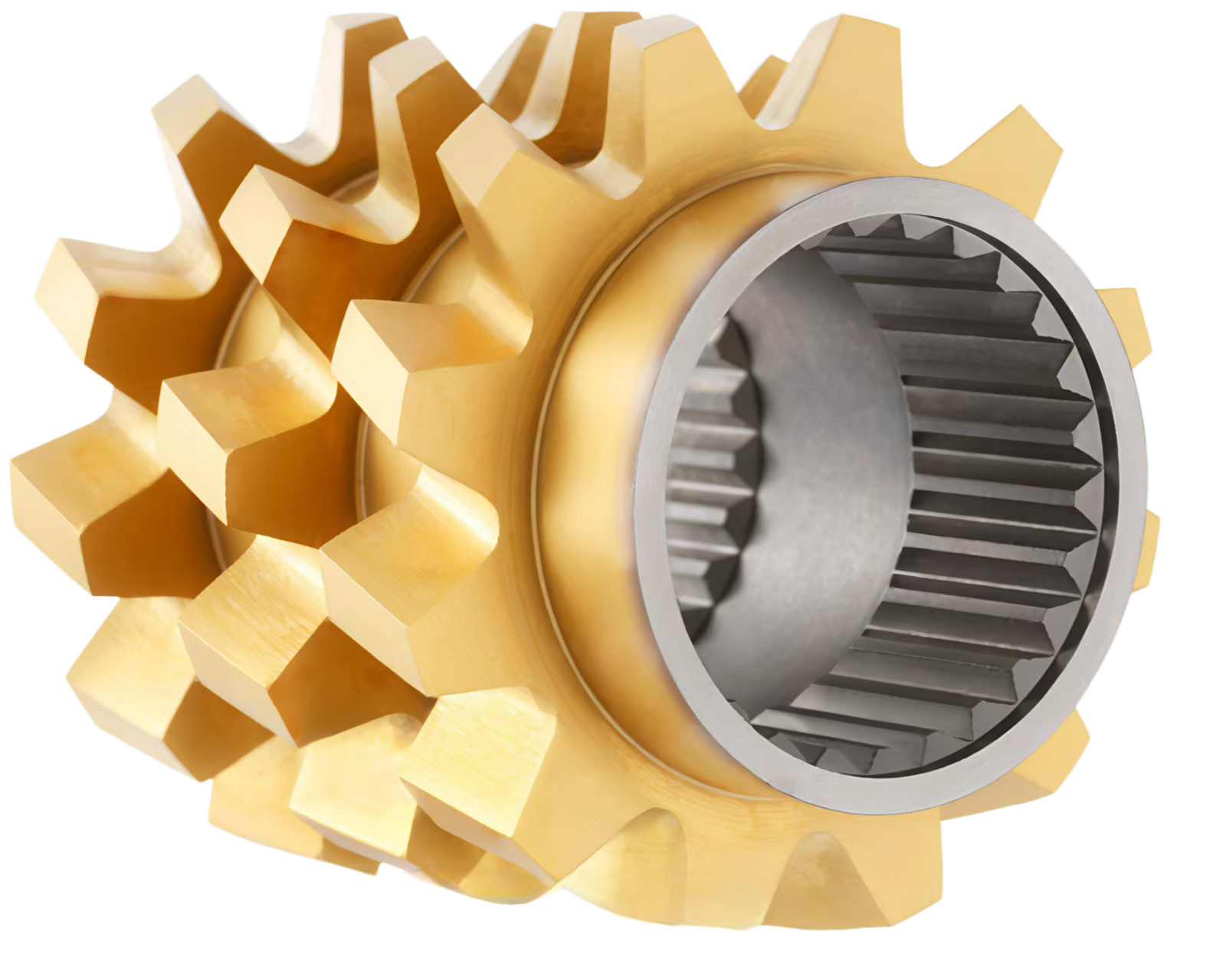
The SME screw element features forward or reverse flighted profiles with milled slots across the flight lands. Manufacturers produce these in 1-start, 2-start, and 3-start geometries. The slots allow leakage flow, splitting and recombining the melt stream continuously as it passes over the screw tips. Unlike standard conveying elements, the SME design disrupts the continuous helical flow. The self-cleaning capabilities of the SME screw element remain robust. The intermeshing action wipes the flanks effectively, preventing material degradation on the screw surfaces.
The width and depth of the milled slots determine the leakage rate. Wider slots allow more material to slip backward over the flight, increasing distributive mixing but reducing conveying efficiency. Engineers select the specific slot geometry based on the viscosity of the polymer melt. High-viscosity melts require wider slots to prevent excessive pressure buildup, while low-viscosity melts need narrower slots to maintain forward momentum.
This element minimizes peak shear rates, keeping viscous heat dissipation exceptionally low. It provides a low-shear, low-energy input ideal for delicate operations. You achieve high distributive mixing efficiency with virtually zero dispersive action. The melt divides at every slot, multiplying the interfacial surface area without subjecting the polymer to intense stress. Forward SMEs maintain pumping capability, reducing downstream pressure drop. Reverse SMEs hold material back, increasing the local fill degree while still prioritizing gentle distribution over harsh shearing.
When you measure the specific mechanical energy (SME) input of a profile heavy in slotted elements, you see a marked decrease compared to kneading block profiles. This low energy input is exactly what you want when incorporating shear-sensitive additives like flame retardants or foaming agents. The material folds and blends without the destructive friction that causes premature activation or degradation.
Use SME elements when processing heat-sensitive resins. They excel with PVC, XLPE, bio-polymers, and engineering plastics highly prone to thermal degradation. They are also perfect for fragile filler incorporation. When distributing glass fibers, carbon fibers, or hollow glass microspheres, maintaining the aspect ratio is critical. The SME prevents physical breakage of these additives. Finally, deploy them for late-stage downstream blending just before the die or vacuum venting dome to ensure final homogenization without adding heat.
Install forward-pitch slotted elements immediately after the side feeder to gently fold glass fibers into the melt.
Use reverse-pitch slotted elements before the vacuum port to create a dynamic seal without overheating the compound.
Combine multiple slotted elements in series to maximize distributive mixing for color masterbatches without degrading the base resin.
Monitor the melt temperature closely; if it drops too low, you may need to increase barrel zone temperatures to compensate for the lack of viscous heating.
The TME screw element consists of gear-like or turbine-shaped discs with straight, neutral-pitch teeth. You will typically find them in variations such as 12-tooth and 24-tooth configurations. This geometry creates radial flow and intense elongational flow between the teeth and the barrel wall. The neutral, non-intermeshing design leads to an absence of self-cleaning. Potential "dead zones" can form in the tooth roots where material may stagnate if not flushed properly by the incoming melt stream.
The straight teeth act as flow disruptors. Because they have no pitch, they do not push material forward or backward. They simply spin, forcing the melt to navigate through the narrow gaps between the teeth. This action creates a highly localized, fully filled zone. The clearance between the outer diameter of the teeth and the barrel wall is critical; tighter clearances increase shear, while looser clearances allow more bypass flow.
The TME screw element provides a balanced shear input. It delivers moderate-to-high shear stress without the extreme local peak shear associated with tight kneading blocks. You gain dual mixing capability: strong distributive mixing combined with highly effective dispersive mixing for soft agglomerates. The neutral pitch dynamics mean there is a complete lack of conveying capability. This characteristic increases local fill degree, pressure drop, and residence time within the mixing zone. The melt must force its way through the turbine gaps, ensuring thorough homogenization.
Elongational flow is the secret weapon of the turbine design. Unlike shear flow, which slides polymer chains past each other, elongational flow stretches the melt. This stretching action is highly effective at breaking down cohesive agglomerates like carbon black or titanium dioxide. The material is pulled apart rather than smashed, resulting in better dispersion with slightly less viscous heating than a comparable kneading block.
Deploy TME elements for color masterbatches and highly filled compounds. They break down stubborn agglomerates in calcium carbonate, talc, and titanium dioxide concentrates. They also perform exceptionally well in polymer alloying. Blending incompatible polymers requires high interfacial surface area generation for compatibilization, which the TME delivers. Additionally, use them as a primary melting zone assist. Placing a TME immediately following the melting zone helps eliminate unmelts and homogenizes the polymer melt temperature before downstream processing.
Application | TME Configuration Strategy | Expected Outcome |
|---|---|---|
Color Masterbatch | Multiple 24-tooth elements in series | Elimination of pigment specks, high color yield |
Polymer Alloying | Alternating TME and conveying elements | High interfacial surface area, stable morphology |
Melting Assist | Single 12-tooth element post-melting zone | Uniform melt temperature, zero unmelts |
The ZME screw element features a multi-toothed profile with numerous small teeth aligned in a reverse-pitch, left-handed configuration. This specific flow mechanism forces the melt to flow backwards and over the teeth. It creates intense splitting, folding, and chaotic back-mixing. The geometric design of the tooth bases makes ZME elements susceptible to material stagnation. The dead spot susceptibility requires careful consideration during formulation changes, as residual material can linger in the root areas.
The reverse pitch is the defining characteristic. It acts as a pump working against the primary flow of the extruder. This forces the material to find alternative paths, usually over the tops of the teeth or through the small gaps between them. The resulting flow field is highly chaotic. The number of teeth and the angle of the reverse pitch dictate the severity of the restriction and the intensity of the back-mixing.
This element delivers high-intensity distributive mixing at moderate shear rates. The reverse pitch generates chaotic flow fields. You get a high frequency of melt division and the creation of complex, non-linear flow paths. The melt constantly folds back on itself. This action results in a massive pressure consumption and localized material hold-up. The reverse-pitch pumping action acts as a dynamic seal, forcing the incoming melt to undergo severe distributive rearrangement before it can bypass the ZME section.
Because the material is held back and constantly folded, the residence time in this specific zone increases dramatically. This extended time at temperature, combined with the chaotic flow, ensures that even the most stubborn, disparate materials are forced to blend. However, this comes at the cost of high pressure drop. You must ensure the upstream conveying elements have enough bite to push the melt through this severe restriction without causing the extruder to surge.
ZME elements dominate in liquid injection zones. They rapidly distribute low-viscosity liquids like plasticizers, oils, silanes, flame retardants, or reactive agents into a high-viscosity polymer melt without phase separation. They are also critical for Reactive Extrusion (REX). The ZME ensures maximum interfacial contact and residence time for chemical grafting, polymerization, or controlled degradation within the barrel. Furthermore, use them for viscosity-contrast blending. When blending polymers with vastly different Melt Flow Indices (MFI), standard elements fail. The ZME forces the low-viscosity phase into the high-viscosity matrix effectively.
Position the liquid injection port immediately upstream of the toothed element to ensure immediate incorporation.
Use aggressive forward-conveying elements before the injection zone to build sufficient pressure to overcome the reverse pitch.
Monitor the injection pressure; if it spikes, the toothed element may be too restrictive for the current throughput rate.
Purge thoroughly when changing formulations, as the reverse-pitch teeth trap material easily.
Avoid using these elements with highly abrasive fillers unless manufactured from premium wear-resistant alloys.
Comparing the specific mechanical energy input reveals distinct operational differences. Rank them by shear intensity: TME provides the highest shear, ZME offers moderate shear, and SME delivers the lowest shear. Evaluate the localized risk of thermal degradation and polymer chain scission based on these profiles. TME elements risk overheating sensitive polymers due to elongational flow and radial shear. ZME elements generate heat primarily through pressure build-up and back-mixing. SME elements pose the lowest risk, making them the safest choice for thermally unstable compounds.
When you analyze the motor torque during a run, a profile heavy in turbine elements will draw significantly more power than a profile using slotted elements. This power translates directly into heat. If your extruder has limited cooling capacity, you must limit the use of high-shear turbine elements and rely more on slotted designs to achieve the necessary distribution without overwhelming the barrel cooling system.
Each element affects the volumetric efficiency of the twin-screw extruder differently. SME elements provide forward-conveying action, generating positive pressure and assisting throughput. TME elements are neutral, creating a high pressure drop and requiring upstream elements to push material through. ZME elements utilize reverse-conveying, creating the highest localized fill and acting as a severe pressure barrier. This impacts the Residence Time Distribution (RTD). SMEs maintain a narrow RTD, while ZMEs create a wide, broad RTD due to extensive back-mixing.
Throughput limitations often trace back to restrictive mixing zones. If you place a reverse-pitch toothed element too close to a vent port, the pressure backup will force polymer out of the vent. You must design the profile with adequate pressure relief zones. Forward-pitch slotted elements are excellent for transitioning out of a high-pressure mixing zone, as they pull material away quickly while still providing distributive mixing.
Evaluate the necessity of specialized wear-resistant materials when processing abrasive compounds. TME and ZME elements often require PM-HIP steels, vanadium-rich alloys, or specialized coatings like TiN or tungsten carbide due to their complex geometries and high localized friction. Purging and cleaning complexity varies significantly. ZME and TME elements are notoriously difficult to purge compared to self-cleaning SME elements. The non-intermeshing teeth and reverse pitches trap material. This increases mechanical burnout times and chemical purging compound consumption during changeovers.
Maintenance crews spend significantly more time cleaning shafts equipped with non-intermeshing teeth. The roots of the teeth hold degraded polymer that standard purging compounds cannot dislodge. You often have to pull the screws and use brass wire wheels or fluidized bed ovens to clean them completely. Factoring in this maintenance downtime is critical when deciding whether to use complex toothed geometries or stick with self-wiping slotted designs.
Technical Parameter | SME Screw Element | TME Screw Element | ZME Screw Element |
|---|---|---|---|
Primary Mixing Mode | Distributive (High) | Dispersive & Distributive (Balanced) | Distributive (Extreme) / Back-Mixing |
Shear Intensity | Low | Moderate to High | Moderate |
Conveying Action | Forward (Positive) | None (Neutral) | Reverse (Negative) |
Pressure Drop | Low (Assists conveying) | High | Very High |
Map your polymer's thermal degradation limits before selecting mixing elements to prevent unwanted chain scission.
Install SME elements downstream for fragile filler incorporation to maintain fiber length and structural integrity.
Utilize TME elements immediately after the melting zone to eliminate unmelts and break down soft agglomerates efficiently.
Deploy ZME elements at liquid injection ports to force low-viscosity additives into high-viscosity melts without pooling.
Audit your current screw profile to identify unnecessary kneading blocks that can be replaced with specialized elements for better temperature control.
A: No. Standard kneading blocks are still necessary for primary melting and high-intensity dispersive mixing of hard agglomerates. Specialized elements complement kneading blocks by handling specific distributive tasks, liquid injection, and temperature-sensitive mixing where traditional blocks cause excessive shear.
A: The ZME element features a reverse-pitch configuration. It actively tries to pump the polymer melt backwards against the primary flow of the extruder. This creates a severe restriction, forcing the melt to build significant upstream pressure to overcome the reverse conveying action.
A: Yes, SME elements maintain the fully intermeshing, self-wiping profile characteristic of standard co-rotating twin-screw elements. The flight flanks wipe each other continuously, preventing material stagnation and degradation on the screw surfaces, unlike the non-intermeshing TME and ZME designs.
A: Because TME and ZME elements have non-intermeshing teeth and dead zones, they require aggressive purging. Use high-viscosity commercial purging compounds and vary the screw speed to dislodge stagnant material. For severe contamination, pulling the screws and performing mechanical wire brushing is necessary.
A: The SME screw element is the best choice for glass fiber incorporation. Its low-shear, forward-conveying design distributes the fibers evenly into the melt matrix without applying the intense dispersive forces that would snap the fibers and reduce the compound's final mechanical strength.


