


Views: 0 Author: Site Editor Publish Time: 2026-07-13 Origin: Site


Poor masterbatch dispersion directly impacts operational efficiency and product quality on the extrusion floor. High scrap rates, color streaking, compromised mechanical properties, and increased customer rejections in downstream conversion processes like film blowing and injection molding usually trace back to inadequate mixing. Standard screw profiles and generic kneading blocks fail to achieve the precise balance of shear and distribution required for highly loaded, shear-sensitive, or temperature-sensitive masterbatches.
Achieving optimal color yield and additive homogeneity requires a strategic configuration of specialized mixing geometries. You must evaluate specific element designs to control melt temperature, residence time, and shear stress accurately. Relying on standard conveying elements for complex formulations leads to un-melted agglomerates and inconsistent color lots. Understanding how to sequence specialized geometries allows operators to optimize extrusion performance, reduce die pressure fluctuations, and ensure consistent masterbatch production without degrading the base polymer.
Masterbatch quality relies on balancing dispersive mixing (breaking agglomerates) and distributive mixing (spatial distribution) without degrading the polymer matrix or organic pigments.
Selecting the correct mixing elements for masterbatch dispersion directly dictates the specific mechanical energy (SME) input, melting rate, and overall extrusion efficiency.
Specialized geometries—such as the SME screw element, TME screw element, and ZME screw element—serve distinct rheological functions and must be sequenced correctly to prevent dead zones, high pressure spikes, and material degradation.
Evaluating screw configurations requires analyzing the trade-offs between aggressive shear for pigment breakdown, wear resistance against abrasive fillers, and the thermal limits of the carrier resin.
Understanding the technical differences between dispersive and distributive mixing dictates how you build your screw profile. Dispersive mixing requires high shear stress to overcome the cohesive strength of solid agglomerates. You need enough mechanical force to break down large pigment clusters into primary particles. Distributive mixing requires continuous flow division, stretching, and recombination. This ensures uniform spatial distribution of the additives throughout the polymer matrix without requiring high threshold shear forces. You use distributive mixing to blend the broken-down particles evenly across the melt stream.
Mixing Type | Primary Mechanism | Target Application | Required Force |
|---|---|---|---|
Dispersive | High shear stress, particle breakdown | Hard pigments, carbon black, agglomerates | High mechanical energy |
Distributive | Flow division, spatial rearrangement | Liquid additives, heat-sensitive dyes | Low to moderate shear |
The viscosity mismatch between the masterbatch carrier resin and the base polymer dictates the required mixing intensity. Carrier resins like wax or low-molecular-weight polyethylene melt quickly. If the carrier melts too fast before the pigments are dispersed, it lubricates the solid agglomerates. This lubrication prevents the screw from applying sufficient shear stress to break the particles apart. You end up with undispersed chunks floating in a low-viscosity melt.
Viscous dissipation limits the use of raw shear power. Pushing high-viscosity melts through tight clearances generates significant viscous heating. Excessive shear heat degrades sensitive polymers and burns organic pigments. You must balance the need for high shear to break agglomerates with the thermal limits of your specific formulation.
Different additives present unique dispersion challenges on the extrusion line. You cannot use the same screw profile for titanium dioxide as you would for a delicate organic dye.
Hard Inorganic Pigments: Materials like TiO2 and iron oxides are highly abrasive. They require controlled shear to break down hard clusters. If you use overly aggressive elements, you will accelerate wear on the screw flights and barrel walls.
Soft Organic Pigments: Phthalocyanines and similar organic pigments possess high cohesive strength and are prone to re-agglomeration. They are highly temperature-sensitive. You must manage thermal input carefully to prevent color shifts or degradation.
Carbon Black: Carbon black has an exceptionally high surface area. It requires massive dispersive energy combined with extensive downstream distribution to achieve optimal color development and prevent surface defects in the final product.
Evaluating dispersion success relies on quantitative criteria. Visual inspection of a blown film sample is not enough for tight quality control.
Filter Pressure Value (FPV) testing according to DIN EN 13900-5 measures the pressure build-up across a standardized screen pack. A rapid pressure increase indicates the presence of undispersed agglomerates blocking the mesh.
Color strength, or tinting strength, measured via spectrophotometry determines the efficiency of pigment utilization. Better dispersion yields higher color strength from the same pigment loading.
Microscopic agglomerate analysis assesses the size and count distribution of remaining particles in a thin film or microtome slice.
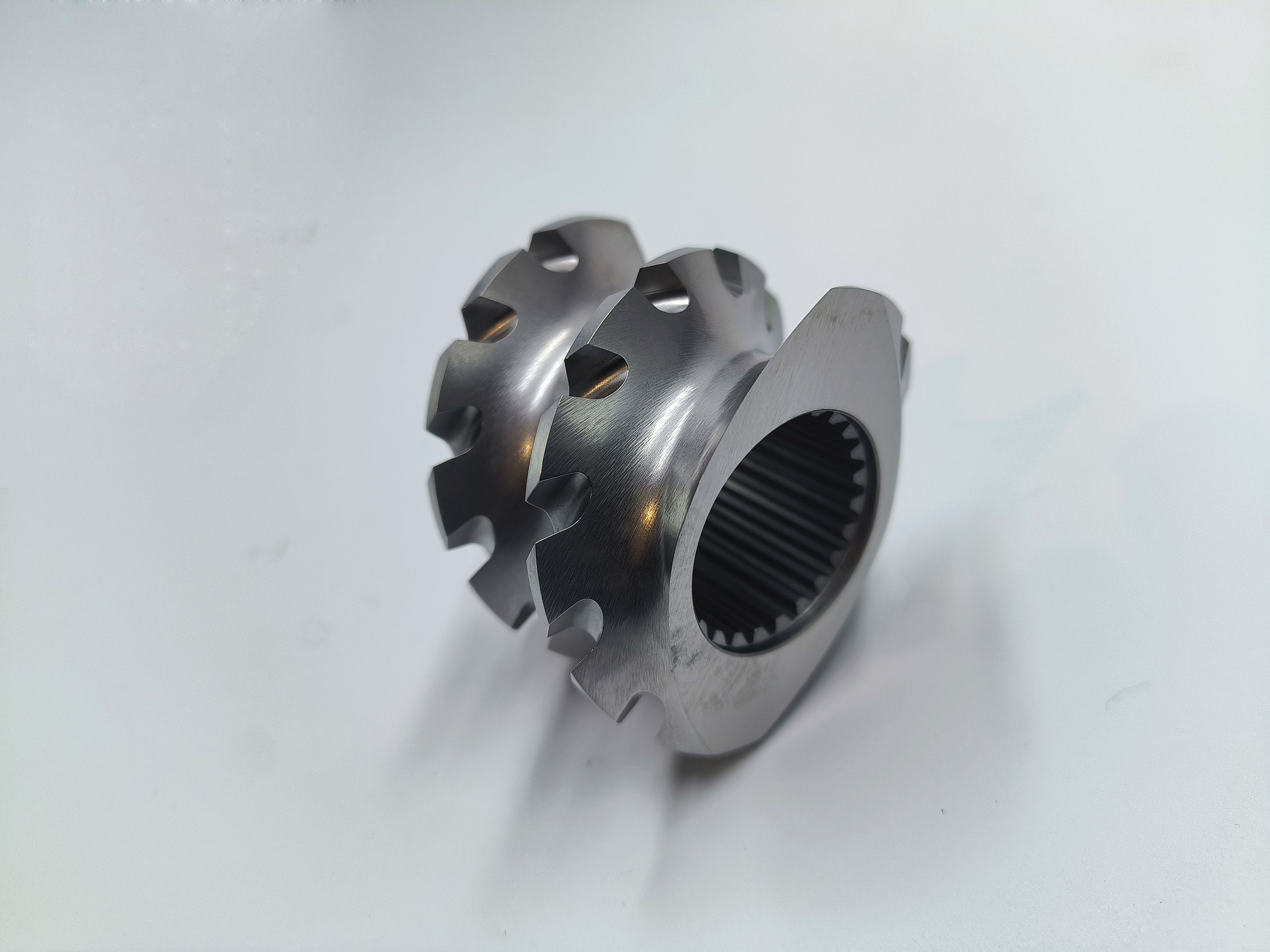
Standard conveying elements and basic 45-degree or 90-degree kneading blocks fall short for complex, high-loading masterbatch formulations. Their rigid shear profiles and poor self-wiping characteristics in critical zones lead to material degradation and inconsistent dispersion. To solve these issues, you must integrate specialized mixing elements for masterbatch dispersion into your extruder configuration.
The SME screw element features a conveying profile with longitudinal slots cut across the screw flights, or sometimes reverse-flighted grooves. This mechanical design excels at distributive mixing. The slots allow a portion of the melt to leak backward over the flights, creating continuous flow division without subjecting the material to high peak shear stresses.
You use this element primarily for low-shear mixing. It is highly effective for reducing thermal degradation and incorporating heat-sensitive additives like organic dyes, chemical foaming agents, or flame retardants. The element achieves uniform spatial distribution without significantly raising the melt temperature. This makes it a critical tool when processing heat-sensitive carrier resins like PET or PLA, where excessive shear heat causes rapid intrinsic viscosity loss.
The TME screw element utilizes a gear-like, toothed geometry. It features multiple small teeth arranged around the screw circumference. As the screw rotates, these teeth continuously split, turn, and recombine the polymer melt stream. The material is forced through the narrow gaps between the teeth, creating a high frequency of flow divisions.
This design is highly effective for distributive mixing. It works exceptionally well for liquid additives, low-viscosity masterbatch formulations, or breaking up striations in color masterbatches. The toothed geometry creates extensive interfacial area generation under moderate shear forces. It prevents local hot spots because the material does not stagnate in high-shear zones. Operators frequently place these elements downstream of the primary melting zone to homogenize the melt temperature before it reaches the die.
The ZME screw element employs a reverse-pitch, multi-flighted design. The channels force the material backward, compelling it to flow over the tight flight clearances to move forward through the extruder. This creates an intense, localized high-shear environment.
This geometry is the premier solution for aggressive, high-shear, dispersive mixing. You need this element when dealing with tough pigment agglomerates like carbon black or highly loaded phthalocyanine pigments. It maximizes local shear stress and elongational flow, tearing apart stubborn particle clusters. However, this intense mixing increases specific energy consumption and localized melt temperature. You must place these elements carefully within the screw profile, usually flanked by forward-conveying elements, to manage the pressure drop and prevent excessive thermal degradation.
Placing specialized mixing elements along the screw length requires precise engineering logic based on the L/D ratio of your extruder. You cannot place high-shear elements randomly and expect good results.
A well-designed screw profile follows a logical progression of melting, dispersion, and distribution.
Feeding and Melting Zone: You start with standard conveying elements to move the solid pellets forward. High-friction kneading blocks are then used to transition the solid polymer and masterbatch carrier into a fully molten state.
Primary Dispersion Zone: This is typically located mid-screw. Here, you place high-shear dispersive elements to break down raw pigment agglomerates. You want to apply this shear at the point of maximum viscosity, right after melting, to transfer the maximum mechanical force to the particles.
Downstream Distribution Zone: After the agglomerates are broken, you integrate distributive mixing elements to homogenize the colorant. This ensures an even color distribution without generating excess shear heat right before the die.
The choice of mixing elements directly impacts the thermal profile of the extrusion process. Over-specifying high-shear elements leads to excessive viscous dissipation. The mechanical energy from the motor converts into heat within the polymer melt. This thermal degradation damages organic pigments, causing color shifts. It also breaks polymer chains, resulting in out-gassing, die drool, and a loss of mechanical properties in the final product. Balancing dispersive power with thermal management is essential. You must monitor melt thermocouples closely and adjust screw speed or barrel temperatures to compensate for the shear heat generated by restrictive elements.
Back-pumping elements and restrictive mixing geometries significantly affect the time material spends in the extruder. A narrow Residence Time Distribution (RTD) ensures consistent, repeatable color properties. If the RTD is too broad, some material stagnates in the barrel, leading to degradation and black specks. Other material passes through too quickly, resulting in undispersed agglomerates. Evaluating how different elements influence RTD helps optimize the process. You want a profile that provides enough residence time for thorough mixing but moves the material through fast enough to prevent thermal damage.
Optimizing a masterbatch extrusion line involves balancing several technical and operational factors. You must look beyond just the visual quality of the pellet and consider how the screw configuration affects the overall process efficiency.
Increasing mixing intensity using restrictive elements often requires reducing screw speed or feed rate to maintain thermal limits. If you push too much material through a highly restrictive high-shear zone, the motor torque will max out, or the melt temperature will spike beyond safe limits. This operational reality impacts overall productivity. Process engineers must balance the need for high-quality dispersion against throughput requirements. You have to find the optimal configuration that delivers acceptable dispersion quality at production rates that meet your output targets.
Masterbatch pigments, such as TiO2, calcined clay, and glass fibers, are highly abrasive. As these hard particles are forced over the tight clearances of mixing elements, they scour the metal surfaces. Specifying advanced materials for complex mixing elements is necessary to maintain critical clearances. Once the flight clearances wear down, the shear stress drops, and dispersion quality plummets.
Powder Metallurgy (PM) steels, such as CPM 10V or CPM 15V, offer superior wear resistance due to their high vanadium carbide content.
Hot Isostatic Pressing (HIP) bimetallic layers provide enhanced durability for barrel sections in high-wear zones.
Specialized surface coatings, like Chromium Nitride or TiAlN, protect against abrasive wear and can extend the lifespan of intricate toothed elements.
The selection of mixing elements directly affects the specific mechanical energy (SME) requirements of the extrusion line. SME is measured in kilowatt-hours per kilogram (kWh/kg). Highly restrictive elements require more motor torque to push the material through, increasing the energy draw. Optimized element geometries can reduce this energy draw while maintaining dispersion quality. By replacing overly aggressive kneading blocks with efficient distributive elements where high shear is not needed, you lower the overall SME input. Evaluating configurations based on their energy efficiency is a critical component of modern process optimization.
Changing a screw profile introduces process risks. You must anticipate these issues and implement strategies to mitigate them before they cause significant downtime or scrap.
Implementation Risk | Root Cause | Mitigation Strategy |
|---|---|---|
Polymer Degradation | Excessive shear from restrictive elements | Integrate low-shear distributive elements; monitor melt temp. |
Dead Zones & Hang-up | Poor transitions, non-wiping profiles | Use fully self-wiping elements; optimize transition angles. |
Venting Failures | Pressure backup from downstream elements | Place deep-channel conveying elements before vent zones. |
Scale-up Discrepancies | Mismatched shear rates between lab and production | Maintain equivalent tip speeds and specific energy input. |
Over-shearing caused by excessive use of high-shear elements or dense kneading blocks leads to severe polymer degradation. The melt temperature spikes, causing the polymer chains to scission. To mitigate this risk, integrate low-shear distributive elements to balance distribution without adding unnecessary shear heat. Additionally, monitor the melt temperature at the die using dynamic melt thermocouples. If the temperature rises too high, you may need to reduce screw speed or redesign the profile to be less restrictive.
Poorly designed transitions between mixing elements and standard conveying elements cause material stagnation. If the melt flow is not streamlined, polymer hangs up in the corners of the channels. This stagnant material degrades over time, eventually breaking loose as black specks or cross-contamination during color changes. Utilize fully self-wiping element profiles to ensure the screws clean each other continuously. Optimize element transition angles to prevent dead zones. Incorporating regular purges with high-viscosity cleaning compounds also helps maintain system cleanliness.
Highly restrictive mixing elements placed too close to degassing zones cause pressure backups. The melt pressure builds up behind the restrictive element and forces the polymer up into the vent port, leading to blockages or vent-flow. This prevents effective moisture and volatile removal. Position forward-conveying elements with deeper channel depths immediately downstream of mixing elements and before the vent. This lowers the local melt pressure, allowing the material to pass under the vent port without flooding it.
Discrepancies between lab-scale dispersion and production-scale output are common. A formulation that disperses perfectly on an 18mm twin-screw might fail completely on a 70mm production line. To mitigate scale-up failures, maintain consistent shear rates and specific energy input across both machines. Scale-up using proven L/D ratios and equivalent tip speeds. Do not rely solely on geometric similarity; focus on matching the rheological conditions the polymer experiences in the high-shear zones.
Optimal masterbatch dispersion requires a bespoke, application-specific combination of specialized elements tailored to the specific pigment chemistry, loading percentage, and carrier resin rheology. There is no universal screw profile that works for every formulation. You must analyze your specific process constraints and material behaviors to design an effective configuration.
Audit your current scrap rates, throughput limits, and FPV data to pinpoint whether your process suffers from a lack of dispersive power or a lack of distributive homogeneity.
Collaborate with extrusion OEM engineers to run computer-aided flow simulations, such as 3D FEM analysis, to visualize shear stress and temperature profiles within proposed screw designs.
Conduct pilot plant trials using your specific masterbatch formulations to validate the dispersion quality and thermal stability before committing to a final production-scale screw configuration.
Establish a routine wear monitoring program for your high-shear elements to ensure dispersion quality does not degrade over time due to increased flight clearances.
A: Dispersive mixing applies high shear stress to break down solid agglomerates into primary particles. Distributive mixing uses flow division and recombination to ensure uniform spatial distribution of those particles throughout the melt without requiring high shear forces.
A: You use this element for low-shear, distributive mixing. It is ideal for incorporating heat-sensitive additives, organic dyes, or flame retardants without significantly raising the melt temperature or causing thermal degradation.
A: This element uses a gear-like, toothed geometry to continuously split, turn, and recombine the melt stream. It provides highly effective distributive mixing, particularly for liquid additives and low-viscosity formulations, preventing local hot spots.
A: Carbon black features exceptionally high surface area and forms tough agglomerates. This element provides the aggressive, high-shear, reverse-pitch mixing needed to tear these clusters apart and achieve optimal color development.
A: Prevent degradation by balancing high-shear dispersive elements with low-shear distributive elements. Continuously monitor the melt temperature with dynamic thermocouples and avoid placing highly restrictive elements consecutively without pressure relief zones.
A: Dead zones occur due to poorly designed transitions between mixing and conveying elements, or the use of non-self-wiping profiles. Material stagnates in these areas, leading to thermal degradation, black specks, and cross-contamination during color changes.


