


Views: 0 Author: Site Editor Publish Time: 2026-07-06 Origin: Site


Maximizing volumetric throughput in twin-screw extrusion often tempts processors to aggressively increase screw pitch. Doing so without calculating the impact on melt pressure can destabilize the entire process. Erratic throughput, surging at the die, and inconsistent melt quality frequently stem from a mismatch between the feed rate, bulk density, and the specific geometry of the conveying sections. When operators push feed rates higher, the immediate reaction is to install longer pitch elements to prevent feed throat bottlenecking. However, this rapid volume expansion drastically alters the pressure gradient inside the barrel. To achieve high-volume production without sacrificing product consistency, engineering teams must critically evaluate how large lead geometries alter the degree of fill, pressure generation, and overall process stability before modifying their screw profiles. Proper profile design requires balancing intake capacity with the necessary compression to maintain a stable melt front.
Volumetric Capacity vs. Pressure: Large lead conveying elements maximize intake and forward transport but generate minimal pressure, requiring careful balancing with downstream restrictive elements.
Degree of Fill Dynamics: Utilizing high-pitch elements lowers the degree of fill in specific zones, which is advantageous for venting but can cause surging if misapplied in melt-pumping zones.
Profile Synergy: Integrating double flighted screw elements with varying pitches ensures a controlled transition from high-volume intake to high-pressure compounding.
Vendor Capabilities: Partnering with a specialized extruder screw elements manufacturer is critical to ensure precise machining tolerances and appropriate metallurgical selection for high-wear, high-throughput applications.
Geometric parameters define how materials move through an extruder barrel. For large lead conveying elements, the pitch typically equals or exceeds the screw diameter. This creates a length-to-diameter (L/D) ratio of 1.0 or higher. Some aggressive intake profiles extend this pitch to 1.5D or even 2.0D. These extended pitches create massive free volume within the barrel, allowing low-density materials to enter the system without bridging.
An inverse relationship exists between pitch size and the degree of fill. If you maintain a constant feed rate and screw speed, a larger pitch spreads the same amount of material over a longer axial distance. The degree of fill drops significantly. This lower fill level prevents material bridging in the main feed zone. However, it severely reduces the element's ability to generate forward pressure against downstream resistance.
Engineers calculate this dynamic using the Specific Throughput formula (Q/N). Here, Q represents the feed rate and N represents the screw speed. Mapping the Q/N ratio to the operational window of large lead geometries reveals their limits. High Q/N ratios demand large free volumes to prevent bottlenecking. Low Q/N ratios in large pitch sections lead to starvation, erratic flow, and poor heat transfer.
Specific Throughput (Q/N) and Pitch Selection Guidelines | |||
Q/N Ratio Range | Recommended Pitch (L/D) | Expected Degree of Fill | Primary Process Function |
|---|---|---|---|
High (> 0.8) | 1.5D - 2.0D | 30% - 45% | High-volume powder intake, deep vacuum venting |
Medium (0.4 - 0.8) | 1.0D - 1.5D | 45% - 65% | Standard pellet feeding, side feeder transition |
Low (< 0.4) | 0.5D - 1.0D | 65% - 90% | Melt pumping, pressure building before dies |
Axial velocity changes drastically based on geometry. Materials conveyed by large lead geometries move forward much faster than those in standard or short-pitch elements. This rapid transport is excellent for clearing the feed throat. It becomes problematic if downstream elements cannot process the volume at the same rate, leading to sudden compaction and pressure spikes.
Flight angle heavily influences conveying efficiency. Solid particulates behave differently than viscous polymer melts. Steep flight angles in large pitch elements push powders and pellets efficiently. Once the material melts, these same angles struggle to grip the viscous fluid, leading to slippage. The Erdmenger profile geometry of self-wiping twin screw conveying elements mitigates some of this by ensuring continuous surface renewal. This wiping action prevents material stagnation and controls localized shearing.
Success in flow dynamics requires steady-state mass transfer. The goal is to move material without inducing localized starvation or over-pressurization. You must balance the rapid forward velocity of large leads with the restrictive nature of kneading blocks. If the transition is too abrupt, the polymer melt will fold back over the flights, destroying throughput stability.
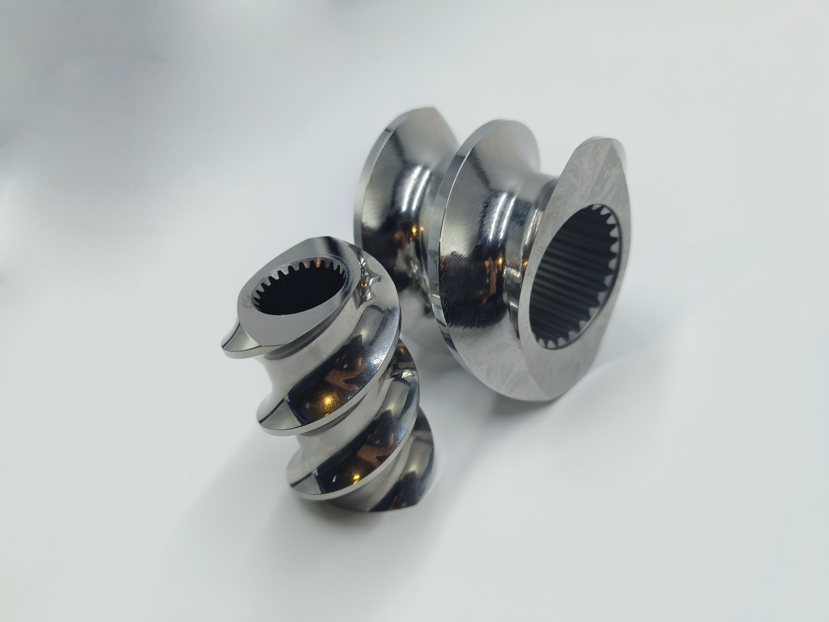
Surging often occurs when large lead elements sit too close to the die. They also cause problems near high-pressure mixing zones. These elements cannot pump against high head pressure. When downstream resistance exceeds their forward conveying capacity, material slips backward over the flights. This creates a pulsing effect at the die lip, ruining dimensional tolerances on the final extruded product.
This backflow destabilizes the entire process. The drag flow versus pressure flow relationship explains this failure. The simplified flow equation is Q = Qd - Qp. Total throughput (Q) equals drag flow (Qd) minus pressure flow (Qp). High-pitch elements have excellent drag flow but suffer massive pressure flow losses under resistance. Their performance drops steeply when pushing into a restrictive die.
Diagnosing pressure instability requires precise data collection and analysis. Follow these steps to isolate the root cause of surging:
Install fast-response melt pressure transducers directly at the die head and before major restrictive kneading zones.
Record pressure data at high sampling rates (minimum 100 Hz) during steady-state operation.
Apply Fast Fourier Transform (FFT) analysis to the pressure signals to extract the dominant frequencies.
Compare the surge frequency to the rotational speed of the screw shaft.
If the frequency matches the rotation of the large pitch elements, redesign the profile to step down the pitch before the restriction.
Rapid forward movement reduces residence time. Material spends less time in the heated barrel zones. This often leads to incomplete melting or poor dispersion of additives. You face a direct trade-off between maximizing throughput and maintaining specific mechanical energy (SME). If the material moves too fast, it does not absorb enough shear energy to melt uniformly.
Optimal compounding requires sufficient SME. If conveying zones push material too fast, downstream kneading blocks must work harder. Forcing kneading blocks to compensate for inadequate pre-heating risks severe thermal degradation. The polymer shears excessively, spiking the melt temperature and potentially burning sensitive additives.
This creates a melting initiation delay. High-pitch conveying sections lack compressive forces. Without compression, air remains trapped, and conductive heating is poor. The material reaches the mixing zone too cold, causing aggressive wear on the kneading elements and degrading the polymer chains through excessive mechanical stress.
High-throughput scenarios require careful element selection. Single flighted designs offer maximum volume but poor stability. Triple flighted designs offer great stability but restrict volume. Double flighted screw elements provide the superior balance. They maintain adequate free volume while delivering excellent conveying efficiency and pressure stability.
Their self-wiping mechanics minimize stagnant zones. This keeps the melt front moving uniformly. To stabilize flow, you must implement a strict transition strategy. Never jump directly from a large lead to a restrictive kneading block. The sudden pressure wall will cause immediate surging and potential torque overloads on the drive motor.
Step down the pitches gradually. Move from 1.5D to 1.0D, then to 0.5D. This gradual reduction compresses the material. It builds pressure steadily and stabilizes the melt front before it hits the restriction zones. This prevents surging, ensures uniform mixing, and keeps the motor torque stable.
The primary objective of the feed zone is intake. You must maximize the intake of low bulk-density materials. Powders, regrind, and lightweight fillers require massive free volume. Large lead elements are mandatory here. They prevent feed throat bottlenecking and stop material bridging above the screws.
Highly cohesive powders require specialized approaches. Standard large leads might not be enough. Integrating undercut elements or specialized intake geometries helps pull sticky powders into the screws. The goal is to move the material away from the feed opening as fast as possible to make room for the incoming raw materials.
Venting zones require a low degree of fill. Typically, you want the fill level below 50 percent. This applies to both atmospheric and vacuum venting. If the fill level gets too high, the polymer will flood the vent port, causing immediate line shutdowns and massive cleanup efforts.
Large lead geometries excel here. They rapidly pull material away from restrictive melt seals. This sudden expansion creates a thin-film distribution along the barrel walls. The increased surface area allows trapped gases, moisture, and volatile monomers to escape easily. Effective devolatilization depends entirely on this rapid volume expansion.
Side feeding ports introduce downstream additives. Glass fibers, talc, and liquid injects enter the melt stream here. The screw profile at this junction must accommodate sudden volume increases. Utilizing large pitch elements at the side feed junction prevents material backup into the side feeder barrel.
These elements ensure consistent volumetric dosing into the main melt stream. They pull the new additives away from the side feeder instantly. This prevents gas entrapment and keeps the side feeder from stalling under backpressure. Proper pitch selection here dictates the accuracy of your final formulation.
Raw material bulk density dictates your maximum allowable pitch. Heavy, dense pellets feed easily. You can use standard pitches without issue. Ultra-fine, aerated powders behave like fluids. High-speed, large lead elements can cause fluidization and aeration in the feed throat, rejecting the powder back up into the hopper.
When powders fluidize, conveying efficiency drops to zero. The screws spin, but nothing moves forward. Mitigation strategies are essential. Utilizing crammer feeders forces the powder into the screws mechanically. Combining crammer feeders with optimized conveying elements stabilizes the intake of difficult materials and maintains a consistent feed rate.
Large lead elements suffer specific wear patterns. The leading edge of the flights takes heavy damage during the acceleration of abrasive compounds. Glass fibers, titanium dioxide, and mineral fillers scour the metal as they are pushed forward rapidly by the steep flight angles.
Wear increases the flight-to-wall and flight-to-flight clearances. This leads to an exponential loss of conveying efficiency. Throughput instability worsens over time as the elements lose their pumping ability. A 10 percent increase in standard clearances can degrade pressure capability by up to 30 percent, forcing operators to increase screw speed to compensate.
Impact of Clearance Wear on Extruder Performance | |||
Clearance Increase (%) | Pressure Loss (%) | Throughput Reduction (%) | Melt Temperature Impact |
|---|---|---|---|
5% | 10% - 15% | 2% - 5% | Negligible |
10% | 25% - 30% | 8% - 12% | +2°C to +5°C (due to shear) |
15%+ | > 45% | > 20% | Severe spiking, degradation risk |
Manufacturer selection dictates profile success. Evaluate manufacturers based on their ability to hold tight clearances. Intermeshing twin screws require tolerances within tens of microns. Loose tolerances cause immediate pressure losses, poor self-wiping, and dead zones where polymer degrades.
Material selection is equally critical. You must match the metallurgy to the process. Nitrided steel works for general polymers. Through-hardened tool steel handles moderate abrasion. Nickel-based alloys survive severe corrosive environments. An expert extruder screw elements manufacturer will guide this selection based on your specific compounds and historical wear data.
Demand proof of quality. ISO 9001 certification is a baseline. Advanced CNC coordinate measuring machines (CMM) are mandatory for verification. If they cannot measure the tolerances accurately, they cannot machine them reliably. Always request inspection reports for new element sets.
Do not settle for simple reverse engineering. Copying existing, potentially flawed geometries solves nothing. Partner with a manufacturer that offers thermodynamic and rheological simulation. 1D and 3D FEM analysis predicts the impact of large lead elements on pressure gradients before you cut any metal.
Evaluate the value of comprehensive engineering support. The best manufacturers provide empirical testing and troubleshooting support. They audit your entire profile. They identify why your current setup surges and design targeted geometric solutions to fix it, ensuring long-term production stability.
Conduct a comprehensive pressure-gradient audit of your current screw profile using transducer data to identify exact locations of pressure loss and surging.
Analyze die pressure variation data using FFT to confirm if large lead elements are placed too close to restriction zones.
Redesign bottlenecked zones by stepping down pitches gradually using double flighted elements to rebuild pressure safely before the die.
Consult with a specialized manufacturer to upgrade the metallurgy of high-pitch intake elements facing severe abrasive wear from glass fibers or fillers.
A: It is a screw element where the pitch is equal to or greater than the screw diameter (L/D ≥ 1.0). These elements are designed to maximize free volume and forward conveying speed, making them ideal for material intake and venting.
A: They generate very little forward pressure. If placed directly before a highly restrictive die or kneading zone, the downstream resistance overcomes their pumping capacity. This causes material to slip backward, resulting in erratic pressure and surging at the die.
A: Double flighted elements should be used when you need a balance of good free volume and stable conveying. They offer superior self-wiping capabilities and better pressure stability than single flighted designs, which are prone to severe backflow under pressure.
A: Larger pitches move material faster axially but lower the degree of fill and pressure generation. Shorter pitches slow the axial movement, increase the degree of fill, and build the pressure necessary to push polymer melts through restrictive downstream dies.
A: If the degree of fill exceeds 50 percent in a venting zone, the polymer melt will likely flood the vent port. This blocks the escape of gases, causes material to extrude out of the vent, and forces a shutdown of the extrusion line.
A: Abrasive wear increases the clearances between the screw flights and the barrel wall. This increased gap allows polymer to leak backward over the flights. As wear progresses, conveying efficiency drops exponentially, leading to severe throughput instability and reduced production rates.


