


Views: 0 Author: Site Editor Publish Time: 2026-07-08 Origin: Site


Unplanned downtime plagues manufacturing lines everywhere. Inconsistent extrusion outputs frustrate operators daily. We often blame temperature swings or bad material batches. Operators waste hours adjusting thermal settings to fix structural flaws. However, the real culprit frequently hides deep inside the machine. Mechanical shaft wear masquerades as simple calibration errors. You cannot afford to guess the root cause of these production bottlenecks.
Replacing a shaft prematurely wastes your valuable maintenance budget. It consumes time and unnecessary labor. Ignoring physical wear invites catastrophic gear failure. You risk severe motor burnout and completely ruined production batches. An unbalanced rotation destroys surrounding components rapidly.
We will explore a proven, evidence-based diagnostic framework. You will learn to evaluate shaft integrity accurately. We will show you how to pinpoint exact failure points using precise tools. Finally, you can make a financially sound repair-versus-replace decision. This systematic approach guarantees long-term equipment reliability.
Diagnostic accuracy saves capital: Identifying specific wear patterns (e.g., torsion fatigue vs. surface galling) prevents replacing parts that only require recalibration or cleaning.
Measurement beats visual checks: A proper extruder shaft inspection relies on micrometers and dial indicators to verify tolerances, not just naked-eye assessments.
Component isolation is critical: Extrusion issues (like slipping or clicking) often stem from adjacent components; the shaft must be isolated before committing to a replacement.
Strategic sourcing: When replacement is unavoidable, matching torque requirements and verifying spline milling shaft specifications ensure long-term equipment stability.
Operators must listen carefully to their machines. Auditory anomalies under load provide the first warning sign. You might hear an infamous clicking sound. Sometimes it manifests as a deep grinding noise. You must distinguish between basic stepper motor skips and mechanical shaft binding. Motor skips often indicate a simple nozzle jam. Continuous grinding points directly to internal shaft friction.
Physical output degradation offers another clear symptom. You will notice physical flaws in your final product. Under-extrusion ruins structural integrity. Inconsistent flow rates cause obvious surface defects. Surging creates uneven layering in the final piece. We can link these flaws directly to potential shaft runout. Gear slippage also produces identical physical extrusion defects.
Torque issues and motor strain act as secondary symptoms. Extruder motors should run at predictable temperatures. Overheating extruder motors signal serious mechanical resistance. You might also notice sudden spikes in power consumption. These power spikes indicate excess friction along the shaft axis. The motor works much harder to overcome a bent component.
Before disassembling the unit, apply the rule of exclusion. You must check readily accessible items first. Examine the nozzle for partial clogs. Verify your filament or resin contains no trapped moisture. Inspect the tension springs for mechanical failure. Eliminate these basic variables immediately. A comprehensive extruder shaft inspection becomes necessary only after ruling out these common operational culprits.
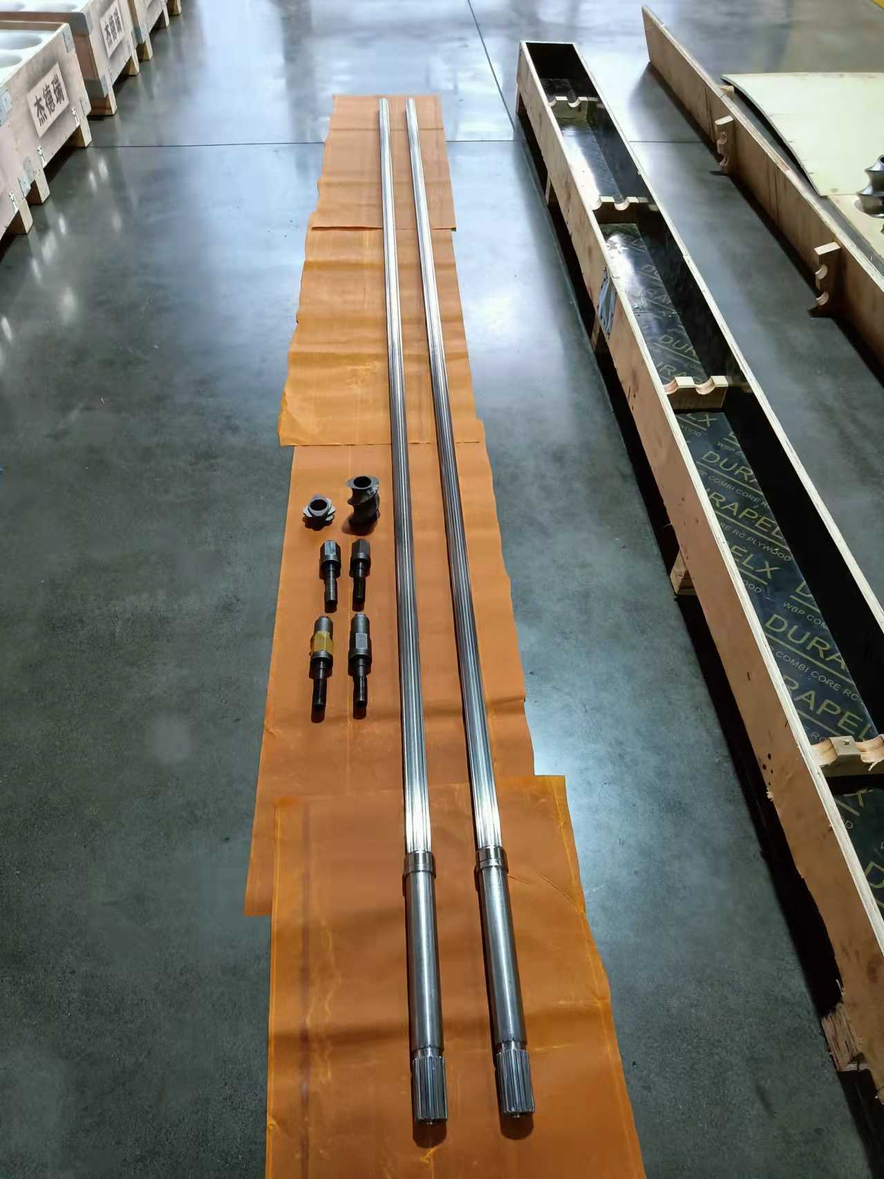
Proper preparation prevents costly mistakes. You must follow strict safety and isolation protocols. Industrial machinery stores immense kinetic and thermal energy. We strongly recommend completing these isolation steps first:
Initiate a complete machine power-down sequence via the main console.
Apply standard lockout/tagout devices to the main electrical breakers.
Allow a mandatory thermal cooldown period for all heated zones.
Relieve any residual pneumatic or hydraulic tension in the drive assembly.
Disconnect the primary motor coupling safely to isolate the rotation.
Skipping these steps risks severe injury. They protect you from sudden unexpected machine movements during disassembly.
Next, gather an essential diagnostic toolkit. Naked-eye assessments fail to detect micro-wear. You need high-precision instruments to measure exact machine tolerances. Your diagnostic kit should include:
Digital calipers for rapid comparative measurements across different components.
Outside micrometers for precise outer diameter wear checks on journals.
Dial indicators equipped with sturdy magnetic bases for runout analysis.
Precision V-blocks to support the shaft during straightness testing.
Magnifying loupes or macro-lenses for micro-fracture visual inspection.
Specialized degreasers to clean mating surfaces before taking measurements.
Finally, you must gather crucial baseline data. Measurements mean nothing without a reference point. Locate your specific OEM machine manual. Reference the original factory dimensional tolerances. Find the acceptable clearance specifications for gears and bearings. Record these baseline numbers on a dedicated inspection sheet. You will compare your physical measurements directly against these strict factory standards.
We divide the inspection into three distinct phases. This structured approach ensures you miss no critical mechanical details.
Phase 1 begins with visual and surface profiling. Clean the entire shaft thoroughly using chemical degreasers. Inspect the bearing journals carefully under strong light. Look closely at all gear-mating surfaces. You are searching for galling, scoring, or pitting. Galling indicates material transfer between moving parts. It creates raised metal lumps on the steel. Scoring looks like deep scratches along the rotational axis. These scratches trap debris and destroy lubrication. You must also identify signs of fretting corrosion. This unique wear often appears as fine red or brown dust. It accumulates exactly where gears mount to the shaft. It signals micro-vibrations between tightly fitted metal parts.
Phase 2 involves dimensional tolerance and runout testing. You will measure shaft straightness precisely. Mount the shaft securely on precision V-blocks. Set up a dial indicator to check for concentricity. Position the indicator tip at the center axis. Rotate the shaft slowly by hand. The dial needle will jump if the shaft bends. This runout test identifies bent shafts instantly. Even a tiny deflection causes severe extrusion surging. You must then verify the integrity of the spline milling shaft section. Splines handle immense rotational torque. Check carefully for rounded spline edges. Look for widened keyways that cause mechanical backlash. A compromised spline section cannot hold a gear tightly. It will slip under high extrusion loads.
Phase 3 requires mating component evaluation. A shaft never operates in isolation. Inspect the corresponding drive gears thoroughly. Examine all supporting bearings and set screws. A worn shaft often damages brand-new bearings rapidly. Conversely, bad bearings will quickly destroy a perfect new shaft. You must evaluate the entire mechanical assembly together.
Inspection Phase | Primary Diagnostic Tool | Key Failure Markers |
|---|---|---|
Visual Profiling | Magnifying Loupe | Galling, scoring, fretting corrosion dust |
Tolerance Testing | Outside Micrometer | Diameter reduction, rounded splines |
Runout Analysis | Dial Indicator | Concentricity deviations, shaft bending |
Component Check | Digital Calipers | Worn gear teeth, loose bearing fits |
After gathering your measurement data, you face a critical operational decision. We use a simple traffic light system. It provides decision-stage clarity and trustworthy cost-benefit analysis.
Green Light means reassemble and monitor. You found only purely cosmetic surface wear. All dimensions remain strictly within OEM tolerances. The runout dial indicator showed negligible needle movement. The solution here is straightforward. Clean the components thoroughly. Lubricate them appropriately using specified greases. Reassemble the unit and safely resume your production runs.
Yellow Light means remediate and plan. You discovered minor scoring on the journals. Your measured tolerances are approaching maximum acceptable clearances. Immediate catastrophic failure remains unlikely for now. The solution requires proactive maintenance. Polish any minor burrs carefully. Replace surrounding consumables like bearings and gears immediately. Most importantly, budget for an extruder shaft replacement during the next scheduled maintenance cycle.
Red Light demands immediate replacement. You cannot safely operate the machinery. A red light triggers when you find measurable bend or runout exceeding operational limits. Sheared, flattened, or compromised splines also mandate instant replacement. Severe galling prevents gears from seating concentrically. Operating under these conditions guarantees a severe mechanical breakdown.
You must understand the economic rationale here. Attempting to machine a warped high-torque shaft is foolish. Trying to straighten hardened steel ruins its structural integrity. It is a false economy. A weakened shaft risks wider machine damage. The cost of a sudden gearbox explosion dwarfs the price of a new shaft.
Status Level | Measured Condition | Recommended Action |
|---|---|---|
Green Light | Within OEM tolerances, zero runout | Clean, lubricate, reassemble |
Yellow Light | Minor scoring, near max clearance | Polish, swap bearings, plan replacement |
Red Light | Bent shaft, sheared splines, deep galling | Halt production, replace immediately |
When replacement becomes unavoidable, you must source replacement parts carefully. You will immediately face OEM versus aftermarket considerations. OEM parts guarantee precise fitment. They eliminate installation guesswork entirely. However, aftermarket alternatives often provide significant cost savings. You must weigh these savings against potential compatibility risks. Proprietary dimensional mismatches cause massive production headaches.
Material and hardening specs demand close attention. You must evaluate shaft materials based on your specific application. Standard extruded plastics require different metallurgy than abrasive carbon-filled composites. Assess options like hardened steel or stainless steel alloys. Look for advanced surface treatments like nitride coating. Nitriding dramatically increases surface hardness. It protects the metal against highly abrasive materials over thousands of hours.
You must verify exact fitment before ordering. Do not rely solely on visual similarities or model names. Cross-reference all critical dimensions manually. Check the overall length and bearing journal diameters. Verify the precise gear pitch and total spline count. These exact measurements guarantee you are purchasing compatible extruder shafts for your specific production line. A single millimeter discrepancy renders the part utterly useless.
Finally, conduct a rigorous vendor evaluation. Establish clear criteria for choosing a supplier. Look for comprehensive warranty coverage on all precision parts. Industrial applications demand certified metallurgy reports. These reports prove the steel grade matches your exact requirements. Review their return policies on precision components carefully. A reputable vendor always stands behind their machining accuracy.
A meticulous inspection routine transforms maintenance from reactive to proactive. It prevents you from treating mere symptoms while ignoring the underlying disease. Guesswork leads to wasted parts and endless troubleshooting loops. Precision measurements tell the true mechanical story every time.
We must reiterate one crucial operational truth. Replacing a shaft represents a precision mechanical upgrade. It is never just a simple parts swap. It requires rigorous post-installation calibration. You must align gears perfectly and tension bearings correctly. Following these steps ensures optimal extrusion performance. Your equipment will run smoother, longer, and much more reliably under heavy loads.
A: Shaft lifespans vary dramatically based on operational variables. A standard unit processing non-abrasive materials might last several years. However, extruding glass-filled or carbon-fiber composites accelerates wear exponentially. Heavy torque loads and continuous production cycles also reduce longevity. Strict adherence to maintenance schedules extends their life. Regular lubrication and prompt bearing replacements prevent premature shaft scoring.
A: Yes, a bent shaft directly causes gear slipping. The mechanics are straightforward. Runout alters the intended gear mesh geometry. As the bent shaft rotates, it pushes the driving gear away from the driven gear. This rhythmic separation creates physical gaps. The gear teeth lose contact, resulting in immediate slipping. This constant engaging and disengaging accelerates tooth wear rapidly.
A: Yes, you should always replace the bearings simultaneously. This represents a critical mechanical best practice. Old bearings develop microscopic wear patterns matching the old shaft. Reusing them transfers those destructive wear patterns directly to your new hardware. Installing fresh bearings prevents immediate scoring. It guarantees concentric rotation and protects your new investment from premature failure.


