


Views: 0 Author: Site Editor Publish Time: 2026-06-17 Origin: Site


Selecting the wrong screw element profile directly impacts extruder throughput. It alters material shear and destabilizes overall process reliability. In bulk material handling and continuous extrusion, the specific flight configuration dictates a critical operational balance. You must carefully weigh available free volume against mechanical energy input. Free volume determines your ultimate feeding capacity. Mechanical energy controls mixing intensity and wiping efficiency. Process engineers and procurement teams require a reliable framework to make these decisions. We provide an evidence-based approach to evaluate these complex geometries. You will learn how to specify the correct flight configuration for your machinery. We explore material behavior, functional zone requirements, and strict production targets. By the end of this guide, you can confidently match the mechanical element to your specific application. This ensures peak performance without starving the feed or stalling the extruder. Proper specification maximizes your production stability daily.
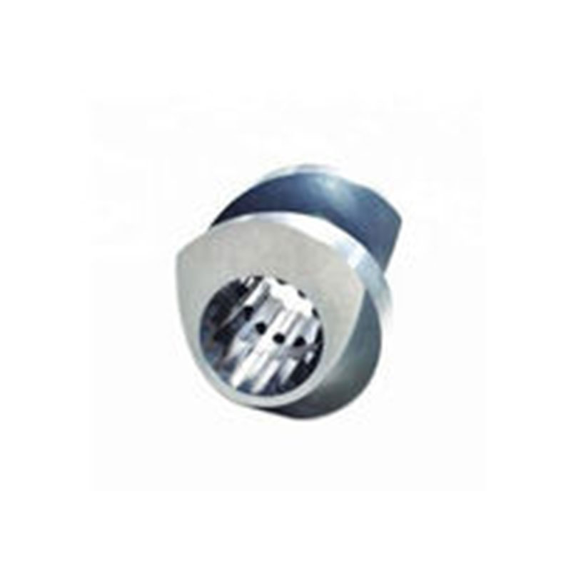
A single-flight screw element maximizes free volume, making it the standard choice for main feeding zones and handling low-bulk-density materials.
Double-flight screw elements offer superior self-wiping characteristics and balanced pressure generation, ideal for melting and mixing zones.
Mixing element types within a single profile requires precise transition engineering to prevent material surging or pressure spikes.
The decision is rarely binary; optimal twin screw extruder elements rely on a hybrid profile mapped to specific process zones (feeding, melting, venting, pumping).
To optimize your extrusion process, you must master elemental geometry. The physical shape dictates how materials flow through the barrel. It also influences the rate of thermal energy transfer. Let us examine the fundamental mechanical differences between these two foundational profiles. Understanding their architecture reveals their distinct operational strengths.
This design features one continuous helical ridge per pitch length. You will immediately notice a deeply cut channel structure. The primary advantage here is sheer physical volume. A single-flight screw element yields the highest possible free volume. It offers the deepest channel depth physically available on a shaft. This creates massive material intake capacity. You can easily feed bulky ingredients into the system.
However, you must accept a distinct mechanical trade-off. The asymmetrical geometry generates completely unbalanced radial forces. During operation, the shaft pushes against one side of the barrel wall. This can accelerate metal wear over time. Additionally, the single ridge design has remarkably lower self-wiping efficiency. It simply cannot clean the intermeshing gaps as effectively as multi-flight designs. You must account for this behavior when processing sticky or cohesive materials.
This configuration features two parallel helical ridges wrapping around the core. The symmetrical cross-section provides immense rotational stability. It inherently balances radial forces during high-speed operation. You gain incredibly stable material conveying. You also achieve a remarkably narrow residence time distribution. The polymer melt moves predictably and uniformly through the heated barrel.
The main trade-off involves greatly reduced free volume. The second flight occupies valuable space inside the conveying channel. This restricts intake capacity for bulky feedstocks. You cannot efficiently feed light powders into a double-flight zone. The elements will quickly choke and stall. They simply lack the physical room to grab large amounts of low-density material. You must reserve them for already compacted materials.
Comparison of Mechanical Characteristics | ||
Parameter | Single-Flight Profile | Double-Flight Profile |
|---|---|---|
Free Volume | Maximum (Deep Channels) | Moderate (Shallow Channels) |
Radial Forces | Unbalanced / Asymmetrical | Balanced / Symmetrical |
Self-Wiping Efficiency | Poor to Moderate | Excellent (Continuous Wipe) |
Shear Generation | Low Shear Input | High Shear Input |
Residence Time | Broader Distribution | Narrow Distribution |
Selecting the right geometry requires systematic performance evaluation. We use specific engineering criteria to guide this critical choice. You must meticulously analyze throughput targets, shear limitations, and cleaning requirements. This prevents costly operational bottlenecks down the line.
You must evaluate material bulk density first. Some materials are highly compressible. Film scrap and lightweight powders behave precisely this way. They demand exceptionally high intake capacity. A single-flight conveying element serves this exact purpose perfectly. It captures massive volumes of air-filled material instantly. It pulls the bulk forward efficiently before it can bridge.
Always calculate your operational fill factor carefully. This metric represents the ratio of actual material volume to available channel volume. If you install a double-flight design here, you severely limit throughput. The required feed rate easily exceeds the element's reduced volumetric capacity. The material will back up into the feed hopper. You will experience severe, unresolvable feed limitations.
Process Engineering Decision Chart | ||
Material Condition | Primary Requirement | Recommended Geometry |
|---|---|---|
Low Bulk Density (Powders) | Maximum Free Volume | Single-Flight |
High Viscosity Melt | Pressure Generation | Double-Flight |
Shear-Sensitive API | Low Heat History | Single-Flight |
Color Masterbatch | Intense Dispersive Mixing | Double-Flight |
Next, assess your specific melting requirements. Double-flight elements introduce much higher shear rates into the polymer. They have multiple crests passing the barrel wall per revolution. Each pass intensely shears the polymer matrix. This generates significant frictional heat internally. It melts the polymer rapidly and ensures a uniform melt pool.
Conversely, single-flight elements impart very low shear forces. This preserves the delicate structural integrity of sensitive materials. You might process delicate PVC formulations regularly. You could be handling shear-sensitive active pharmaceutical ingredients daily. High shear would degrade these expensive compounds instantly. Single-flight designs protect them from catastrophic thermal degradation.
In co-rotating twin screw extruders, thorough wiping is absolutely crucial. Double-flight elements provide a continuous, tight self-wiping profile. The crest of one element actively wipes the flank of the adjacent one. This prevents viscous material from sticking permanently. It leaves no dead zones behind during rotation.
Single-flight elements have distinctly larger gaps in the intermeshing zone. They cannot wipe each other completely during a revolution. This naturally increases the risk of material hang-up. Unwiped material stagnates against the warm metal. It degrades over time and causes carbonized black specks. It also leads to much longer residence times. You must carefully position single-flight sections to avoid these severe quality defects.
You should deploy single-flight geometries highly strategically. They excel in specific processing zones where volume constraints dominate. They solve intake problems other geometries cannot handle. Let us look at the primary applications for this design.
Main Feeding Zones: These elements are absolutely essential for maximizing material intake. They aggressively pull bulk ingredients directly from the hopper. They prevent fluffy materials from floating above the screw.
Side Feeding and Stuffing: You often need to introduce high volumes of downstream fillers. Talc and glass fibers are common industrial examples. The deep channels accommodate these incredibly bulky additives easily. They draw them into the melt efficiently.
Venting and Degassing Zones: Extrusion naturally releases trapped moisture and volatile gases. You must extract them forcefully through a vacuum port. The large free volume keeps the polymer melt low inside the channel. This prevents the expanding melt from rising and flooding the vent port.
Handling Difficult Feedstocks: Cohesive or extremely sticky materials bridge easily inside hoppers. They clog multi-flight geometries instantly. A single-flight profile remains wide open and highly functional. It handles challenging, low-density materials effortlessly.
Double-flight screw elements absolutely dominate the active processing zones. They aggressively manipulate the viscous melt. They apply intense mechanical energy and build necessary pressure. They provide the backbone of the extrusion process.
Melting and Plastication Zones: The symmetrical geometry facilitates incredibly rapid energy transfer. Higher shear generates uniform melting across the entire polymer matrix. They convert solid pellets into a homogenous fluid quickly.
Distributive and Dispersive Mixing: These elements serve as the reliable standard baseline. You build your complex mixing blocks and kneading elements upon them. They ensure additives disperse evenly throughout the batch.
Pumping and Discharge Zones: You need incredibly stable pressure at the die head. Double-flight designs provide flawless, pulsation-free pressure generation. They ensure perfectly consistent output and highly uniform product dimensions.
Fact vs. Myth: A common misconception states they are universally better for all extrusion processes. This is completely false. Using them in feeding zones for low-density materials is a severe engineering error. It will cause immediate feed limitation. It will starve the extruder completely and ruin throughput.
Deploying various flight profiles carries inherent mechanical risks. You must actively manage severe mechanical stresses and strict industry regulations. Twin screw extruder elements require precise engineering to function together flawlessly. Misapplying them leads to catastrophic equipment failure.
Single-flight elements face entirely unique mechanical challenges. They are subject to continuous asymmetrical deflection. The unbalanced radial forces aggressively push the shaft off-center. This can rapidly accelerate wear on the element crest. It also wears down the expensive barrel wall if not adequately supported.
You must mandate strict tolerance checks during all maintenance cycles. Measure the crest-to-wall clearance regularly using precise gauges. Replace worn elements promptly to maintain process stability. You might need highly specialized metallurgy to resist this localized abrasion. Hardened tool steels or advanced carbide coatings significantly extend the operational lifespan. Ignoring wear leads to severe pressure drops.
Regulated industries mandate exceptionally strict hygiene protocols. For food extrusion, internal stagnation areas pose severe biological risks. Single-flight geometries inherently contain unwiped hidden zones. These areas inevitably trap organic residue. Dangerous bacterial growth can easily occur. Cross-contamination becomes a constant, unacceptable threat.
Regulatory bodies often reject these designs outright for sanitary applications. They legally mandate double-flight, fully self-wiping profiles. These strict designs are necessary for clean-in-place (CIP) compatibility. They ensure absolutely no material remains behind after the production run ends. You must follow these guidelines to pass crucial facility audits.
You rarely build an entire shaft using only one element type. Transitioning from a single-flight to a double-flight design is mathematically complex. You cannot simply place them next to each other on the spline. This creates a severe physical bottleneck.
This requirement demands specialized transition elements. These unique pieces compress the material incredibly smoothly. They guide the flow from a deep channel directly into a shallow one. They avoid abrupt, dangerous pressure spikes inside the barrel. They also prevent severe mechanical torsion on the shaft itself. Proper transition engineering ensures a continuous, smooth flow without surging.
We must summarize our strategic engineering approach clearly. The choice depends entirely on the specific functional zone of the extruder. Single-flight elements permanently solve volume and bulk feeding constraints. Double-flight elements effectively solve mixing, wiping, and pressure stability requirements. Both play vital roles in a balanced system.
Here are your immediate next steps for optimization:
Audit your current screw profile thoroughly for any mismatched zones.
Identify areas experiencing recurring feed limitations or unexpected vent flooding.
Replace choked double-flight feed sections with single-flight alternatives immediately.
Consult an engineering partner to mathematically model your transition points.
Verify your chosen metallurgy effectively matches the expected radial wear patterns.
Optimizing this delicate geometric balance guarantees a significantly more stable, highly productive extrusion process.
A: Yes, this is standard practice in compounding. However, it requires engineered transition pieces to align the flight crests and safely compress the free volume.
A: A longer pitch increases conveying speed but reduces pressure generation. A shorter pitch increases the degree of fill and pressure but reduces conveying speed.
A: Usually not. Spline designs, centerline distances, and specific clearance tolerances vary by OEM. Always verify shaft compatibility and metallurgy before replacing elements.


