


Views: 0 Author: Site Editor Publish Time: 2026-06-05 Origin: Site


Increasing throughput or adding complex fillers often leads to a common, frustrating production bottleneck. Relying solely on standard top-feeding methods can trigger premature material degradation, erratic melt pressure fluctuations, or severe screw wear. You might notice these specific issues consistently stalling your output rates and hurting overall product consistency. Upgrading a side feeder extrusion line goes far beyond a simple capacity play. It represents a precise metallurgical and chemical decision tailored for your unique manufacturing process. Properly introducing materials downstream completely transforms how base polymers melt, mix, and perform. This guide will break down the exact process symptoms and material characteristics you must watch for today. We will explore the integration realities justifying the capital expenditure of adding advanced side-feeding capabilities. You will learn how to protect expensive equipment while simultaneously maximizing your total throughput yield.
Side feeding is virtually mandatory for high-volume abrasive fillers (like glass fiber) to prevent catastrophic wear on the main melting zone.
Low bulk density materials (powders, talc) require downstream side feeding to prevent fluidization and bridging in the main hopper.
Integrating a side-feed barrel system requires recalculating the extruder’s L/D profile and upgrading control systems for synchronized RPMs.
While side feeders improve compound quality, they introduce new maintenance variables regarding specific extrusion line spare parts and cleaning protocols.
Many operators face hidden, persistent bottlenecks when pushing their equipment to the absolute limit. We see specific, repeatable symptoms emerge when processes outgrow standard top-feeding methods. Recognizing these early warning signs helps you prevent unplanned downtime and wasted material.
Light powders displace air rapidly. When you feed them into the main throat alongside polymer pellets, they cause severe "fluffing" or bridging. This phenomenon caps your maximum throughput regardless of how fast you run the main screw. Aerated materials simply refuse to convey efficiently down the barrel. The trapped air pushes back against the incoming feed, creating a pneumatic lock. You end up starving the screw, dropping overall output, and experiencing wild surges at the die. By forcing light powders through the top, you restrict the physical free volume available for the much heavier polymer pellets.
Heat-sensitive additives demand careful, deliberate handling. Introducing flame retardants or specific powder coating pigments into the primary melting zone is highly risky. The initial sections of the screw utilize high-shear forces to generate intense friction and mechanical heat. This aggressive environment degrades sensitive organics before they ever reach the die. You lose functional properties, ruin product color, and often generate hazardous off-gases. Cross-linking agents can trigger prematurely, creating hard gels causing contamination in the final batch.
Feeding abrasive materials through the main throat carries severe, compounding maintenance consequences. Hard fillers act like coarse sandpaper against your primary screw elements and barrel walls. This degrades your metallurgy exponentially faster than introducing fillers downstream. The solid conveying and melting zones experience the highest pressures and radial forces. When you force abrasives through these zones dry, the metal-to-metal and metal-to-mineral friction spikes. Downstream injection pushes abrasives into an already existing, fully fluid melt pool. The molten polymer lubricates the interaction and protects your hardware from catastrophic early failure.
Understanding the fundamental physics between different feeding locations ensures better overall process design. Top feeding and side feeding serve entirely different metallurgical and thermodynamic purposes.
Top feeding works best for robust, high-density base polymers. Standard plastic pellets require maximum shear and extended residence times. They need this intense mechanical energy to melt completely and uniformly. The primary feed throat excels at delivering massive mechanical work to solid pellets. It utilizes deep-flighted screw elements to grab the solids, compress them, and transition them into a fluid state through intense frictional heating.
Side feeding changes the physical dynamic entirely. You introduce new materials into an already molten, highly viscous polymer matrix. The melt acts as a fluid carrier for the incoming particles. This prevents aggressive dry friction and drastically lowers the required mixing energy. Instead of grinding solids together, the side mechanism gently folds the additive into the liquid phase.
To visualize these differences, we use a simple feature-to-outcome comparison chart to guide operational choices.
Process Feature | Top Feeding Outcome | Side Feeding Outcome |
|---|---|---|
Dispersion | Delivers intense dispersive mixing with high stress to break down tough agglomerates. | Provides gentle distributive mixing to fold and spread materials evenly into the melt. |
Fiber Integrity | Destroys the structural aspect ratios of glass or carbon fibers due to high shear forces. | Preserves fiber length and physical strength by entirely bypassing the aggressive melting zone. |
Throughput Yield | Shares limited volumetric capacity between base resin pellets and bulky filler powders. | Separates the feeds to maximize the physical volumetric capacity of the entire extruder. |
Certain material profiles make downstream feeding an absolute necessity. You cannot achieve optimal compound quality or equipment lifespan without it. Implementing a twin screw side feeder becomes the standard industry practice for these specific, demanding formulations.
Glass fibers, mineral fillers, and silica compounds destroy standard conveying elements quickly. We rely on a co-rotating mechanism to limit abrasive wear strictly to downstream elements. The base polymer is already fully plasticized at this stage. It coats the abrasive particles instantly upon entry. This rapidly reduces direct metal-to-mineral contact. For glass fiber specifically, preserving the strand length is critical for the final tensile strength of the plastic part. High-shear melting zones would chop these fibers into useless dust.
Talc and calcium carbonate present massive handling challenges due to their lightweight nature. They fluidize easily and resist falling cleanly into a standard screw flight. Twin-screw mechanisms actively "bite" into aerated powders. They compress and convey these light materials directly into the pressurized melt. This method entirely bypasses main throat fluidization. You avoid the notorious dust clouds, bridging issues, and feed-throat blockages seen at the primary hopper.
Minimizing residence time is critical for organic pigments and specialty cross-linking agents. Powder coatings also react poorly to prolonged heat exposure. Introducing them downstream minimizes their exposure to both thermal and shear stress. They spend only a fraction of the time inside the heated barrel compared to base resins. This precise timing prevents unwanted thermal degradation, color shifting, and premature curing inside the machine.
Best Practice: Always pre-blend highly cohesive powders with a trace amount of flow aid before introducing them to the feeder hopper. This prevents rat-holing inside the dosing bin.
Adding a lateral feeding mechanism is not a simple plug-and-play operation. It requires a precise architectural redesign of your current setup. You must meticulously modify the barrel layout, venting locations, and control logic to accommodate the new input stream.
You must position the side-feed barrel system carefully along the extruder profile. Technical guidance dictates placing it downstream after the polymer is fully plasticized. However, you must leave enough L/D (Length to Diameter ratio) for adequate distributive mixing before the die. Placing it too close to the discharge results in poor homogenization and visual defects. Placing it too far upstream risks premature wear and unnecessary thermal exposure for the additives. Most engineers target the middle-to-late sections of the extruder, typically around the 24 to 32 L/D mark, depending on the overall machine length.
Lateral feeding mechanisms introduce massive amounts of trapped air alongside the fillers. You face a critical need for proper venting. Upstream or immediate downstream atmospheric venting is mandatory to extract the air introduced by the unit. Vacuum venting further down the line extracts any remaining volatiles or moisture. Without proper degassing, you will suffer from severe porosity, bubbles, and surface defects in your final extruded product.
Implementation realities demand advanced digital controls. The auxiliary unit's RPM must be digitally slaved to the main extruder’s RPM. It must also communicate seamlessly with the gravimetric loss-in-weight feeders to maintain strict formulation ratios. If the main screw slows down due to a pressure spike, the lateral unit must reduce its speed instantly. This closed-loop communication prevents localized overfeeding, material packing, and sudden torque overloads.
Common Mistake: Ignoring the internal pressure gradient at the injection port. If melt pressure is too high at the insertion point, the molten polymer will flow backward into the auxiliary unit, causing a catastrophic jam.
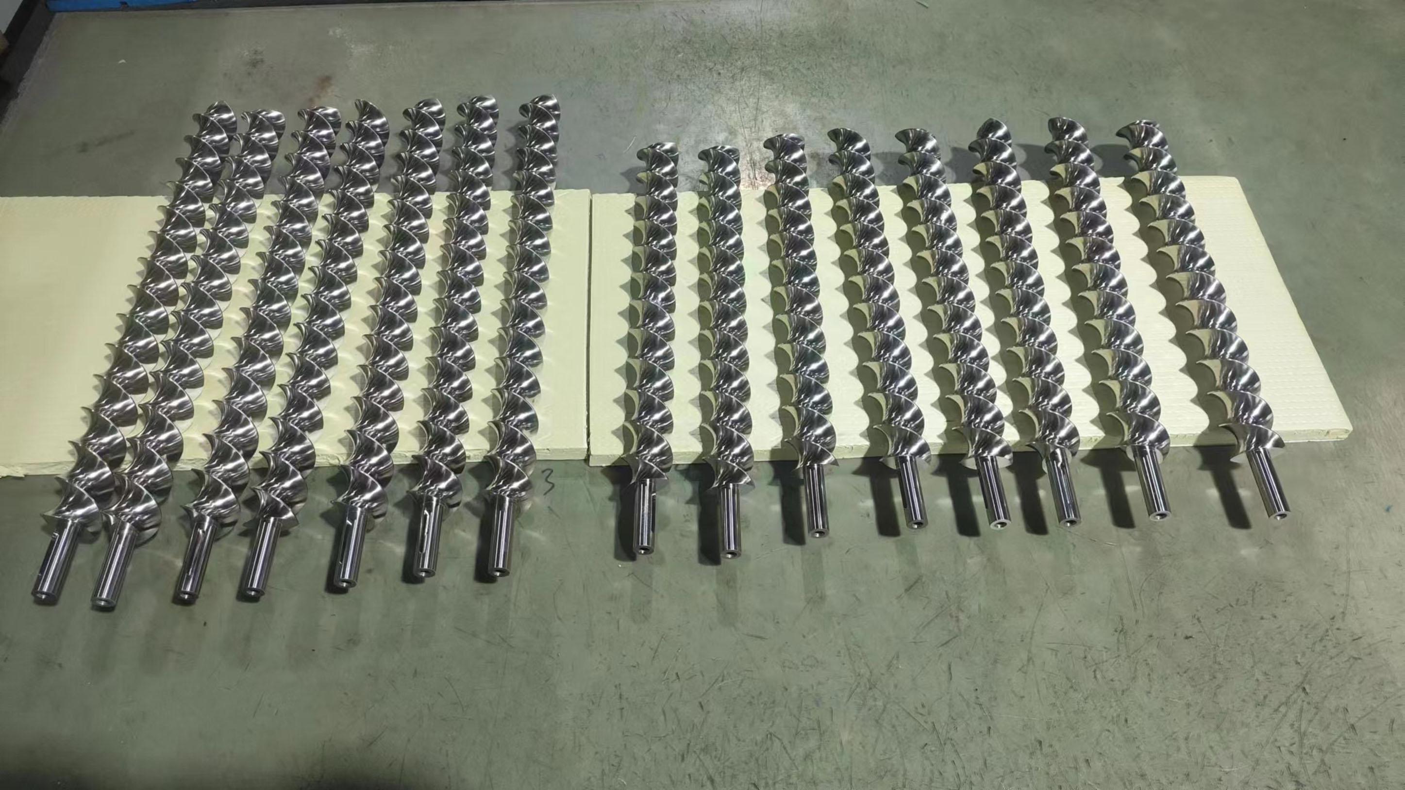
We must be transparent about the operational impact of upgrading your equipment. Adding lateral capabilities introduces a secondary set of wear components into your ecosystem. You now have multiple sets of screws, shafts, and barrels to monitor daily.
While downstream injection saves your primary melting zone, abrasive materials will still wear down the downstream mixing elements. This wear simply happens at a more manageable, predictable rate. You shift the mechanical burden from the most expensive primary screws to the more accessible secondary units. Regular tolerance checks using precision gauges become a necessary weekly maintenance task.
Smart inventory management prevents extended, costly downtime. Operators must proactively stock critical extrusion line spare parts to keep production running smoothly. You should always maintain a ready inventory of the following components:
Splined shafts for the secondary drive mechanisms to prevent fatigue failures.
Specific conveying elements designed for high-volume powder transport.
Replacement barrel liners dedicated exclusively to the lateral unit.
Specialized sealing rings to prevent melt leakage at the high-pressure connection port.
More equipment inherently means more internal surface area to clean. This introduces an operational risk of longer color or material changeovers. To mitigate this downtime, prioritize quick-release swing-arm mounts on your machinery. Slide-out rail systems also allow operators to pull the unit away rapidly for inspection. These mechanical features turn what could be a four-hour teardown into a highly efficient thirty-minute cleaning cycle.
Side feeders act as process-critical upgrades for handling abrasives, low-density powders, and heat-sensitive materials. They successfully shift production limitations away from equipment capability and focus purely on your specific formulation limits. By preserving filler integrity and isolating mechanical wear, you extend the lifespan of your primary machinery while unlocking new material capabilities.
Process engineers should begin by conducting a baseline wear analysis on their current main screws. Document your existing maximum throughput before making any permanent layout changes. Run a localized pilot test to measure exact throughput gains and temperature variations. Validating these metrics ensures your retrofit delivers the expected performance and quality improvements.
A: Yes, provided you can swap a closed barrel section for a side-feed barrel system and update the PLC to handle the additional drive and gravimetric data.
A: Yes. To ensure strict recipe adherence, the side feeder must be paired with a dedicated loss-in-weight feeder positioned directly above it.
A: It typically improves them significantly by preserving filler structures (like fiber length) and preventing the thermal degradation of sensitive impact modifiers.


